
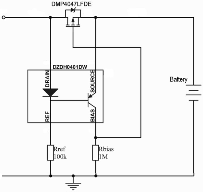
Called DZDH0401DW, it is designed to work with a p-channel mosfet in the high-side rail in systems up to 40V.
It might better be describes as a ‘nearly ideal diode controlled’ as it draws some current from the output circuit when no input is connected – 147μA if a 12V battery is connected to the output in the data sheet battery charging example (100kΩ Ref, 1MΩ Rbias)
The circuit senses using the differential voltage drop between two junctions operating at different currents – the diode junction and base-emitter junction (see diagram). The diode is operating at higher current (loaded by 100kΩ compared with 1MΩ in the example) and therefor has the higher voltage drop.
At switch-on, the external mosfet’s parasitic diode initially supplies the load, with the mosfet turning on and carrying the load current shortly afterwards – once the mosfet’s gate capacitance has charged via Rbias.
During the mosfet turn on, at some point the junction voltage drop difference will slightly turn the pnp on and the IC will act to regulate the drop across the mosfet to a small value a little above its minimum possible value. “Vgs should be high enough at this point to ensure linear operation,” according to Diodes.
When the supply is removed, the mosfet will still be on and would support the input terminal, except that the voltage across the mosfet is now zero (almost, as the load of Rref will make it very slightly negative), causing the difference in junction voltages to turn the pnp on properly, at which point its low Vce will turn the mosfet hard off.
Rref has some control over turn-off speed, as it sets the pnp’s base current and therefore the pnp’s ability to discharge the mosfet’s gate current.
Once ‘off’, the battery continues to drain through Rref and Rbias. “These resistors’ values are chosen to minimise quiescent current operation of the circuit,” said the company.
The IC’s diode prevents leakage back into the supply if this circuit is used as part of a power rail OR-ing arrangement. Maximum reverse protection is 50V, and peak allowable bias is -300mA.
In a 12V battery charging example, with Rref=100kΩ, Rbias=1MΩ and a DMP4047LFDE mosfet, the data sheet includes the following figures:
| Input connected |
Input open-circuit |
|
| Input V | 14.1V | – |
| Input I | 3A | 0 |
| Output V | 14V | 14V |
| Output I | 3A | -147μA |
| Diode Vf | 600mV | – |
| Diode If | 135μA | 0 |
| Vref | 13.4V | 13.3V |
| Iref | 136.6μA | 133μA |
| Ibase | 1.6μA | 133μA |
| Iemitter | 12.1μA | 145μA |
| Vbias | 10.5V | 13.94V |
| Icollector | 10.5uA | 13.94V |
| Iground | 147μA | 147μA |
(Table slightly modified, and errors might have been introduced during transcription)
Applications are expected in cordless power tools, smart vacuum cleaners, smart lawnmowers, OR-ing rectifiers and, for data centre servers, hot-swappable and N+1 redundant power supplies.
The device comes in a 2.15 x 2.1 x 1mm SOT363 package. It is manufactured in IATF 16949 certified facilities.


![W88 [Rủi Ro Khi Chơi Nổ Hũ: Lưu Ý Quan Trọng Nhất Cho Người Chơi]](https://theskil.com/wp-content/themes/rehub-theme/images/default/noimage_336_220.png)