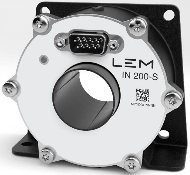
Called IN 200-S, the sensor is rated at up to ±200A (dc or ac(rms), 300A peak) and is design to be a measuring instrument for the development and testing of inverters using in electric vehicles and hybrid vehicles.
Bandwidth is dc to 1.1MHz (-3dB), and the conductor aperture is 28mm – the transducer is ~70mm in diameter.
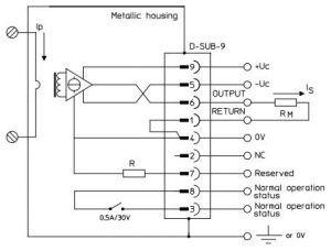
The output is a current, which needs an external precision resistor between 0Ω and 15Ω to turn it into a voltage. Higher resistor values are possible, at the expense of reduced current measurement range.
 Overloads are indicated by the built-in status LED turning off, a status pin being pulled to 0V, and a floating normally-shorted pair of interlock pins being opened. All connections are through a 9pin D-Sub connector, alongside the three pins that carry the ±15Vdc power supply. High power supply wiring resistance can also reduce current measurement range.
Inside, the technology is fluxgate, with the company switching from analogue processing to digital signal path processing. “Traditionally, many analogue circuits would be required to cancel out noise and other impacts of having different fluxgate coils but LEM’s solution reduces substantially the number of analogue circuits,” it said.
Digital processing is used for ripple compensation, second harmonic detection, voltage regulator excitation and to extent temperature range, to -40°C to +85°C, and supply voltage rejection.
A switch to metal casing has improved EMC rejection, and reduced temperature drift, said LEM. The case is designed to be panel-mounted.
Insulation is reinforced 10 1kV according to IEC 61010-1 CAT II, PD2 – with a non insulated busbar completely filling the aperture – max altitude is 2,000m.
Other applications are for feedback in MRI gradient amplifiers and feedback in precision power supplies.
IN 100-S and IN 400-S are also available.
The IN 200-S product page is here, and its data sheet is here


![W88 [Rủi Ro Khi Chơi Nổ Hũ: Lưu Ý Quan Trọng Nhất Cho Người Chơi]](https://theskil.com/wp-content/themes/rehub-theme/images/default/noimage_336_220.png)

